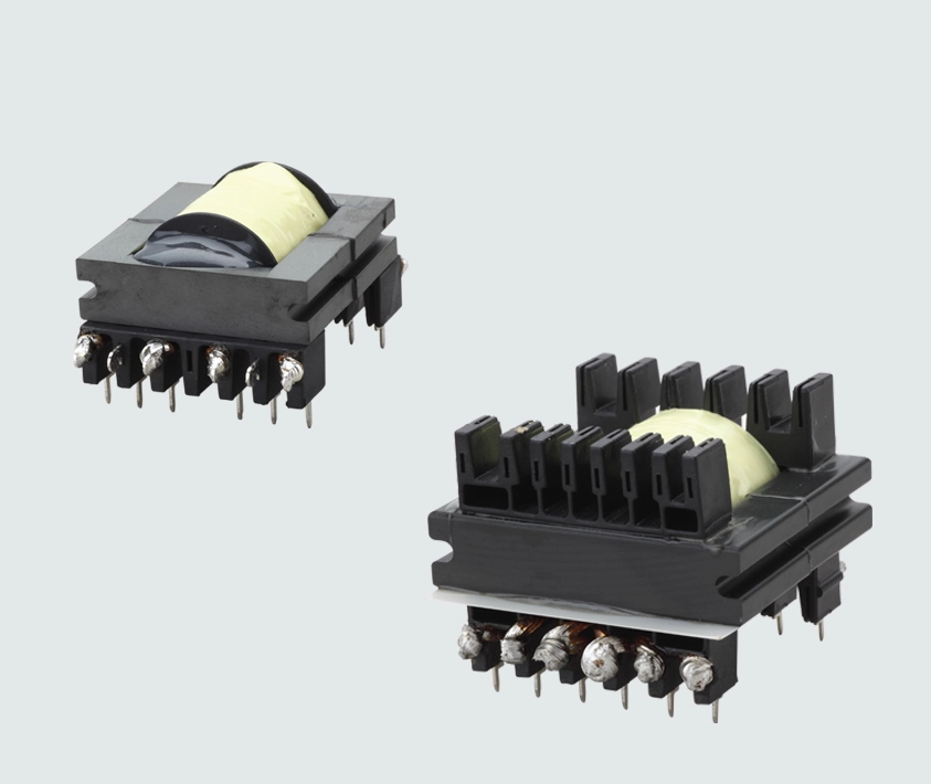
Ask a power supply engineer what slows a project down and you’ll often hear about the magnetics. Not because they’re mysterious, but because they’re custom, they interact with everything else on the board, and a small miscommunication with the supplier can cost weeks.
Start with the circuit, not the part
A magnetic component isn’t designed in isolation. Its behaviour depends on the topology, frequency, voltages, currents, and the surrounding components. Give your supplier the following:
• Topology: flyback, forward, half-bridge, LLC, PFC, and so on.
• Input and output voltages and currents, including worst cases.
• Switching frequency and any variation.
• Duty cycle ranges.
• Ambient temperature and cooling conditions.
• Size limits and mounting style.
• Safety standards and insulation requirements.
A schematic or the relevant section of it is even better than a list of numbers.
Core material: the heart of the matter
The core material decides efficiency, size, and behaviour under load.
Ferrite is the common choice for transformers and inductors in switching supplies. It has low losses at high frequencies, which is why it’s so widely used.
Nanocrystalline cores offer very high permeability and good temperature stability, which makes them excellent for common mode chokes aimed at suppressing noise across a wide frequency range. They’re also used in some high-performance transformers.
Powder cores, such as iron-silicon, sendust, or similar materials, handle DC bias well and have a soft saturation characteristic, which suits many inductors that carry a large DC current.
The right choice depends on frequency, current, temperature, and cost.
Saturation and the high current inductor trap
When you specify a high current inductor, you’ll see two current ratings: the saturation current and the heating current. Saturation current is where the inductance falls by a set percentage; beyond it the inductor stops behaving like an inductor. Heating current is where the temperature rise reaches a set limit. Check both, and always check what the drop percentage and temperature rise conditions are—manufacturers define them differently.
Winding resistance matters too. Lower DC resistance means less heat, which often means using thicker or flat wire, and that affects the size.
Skin effect and winding choices
At higher frequencies, current flows toward the surface of a conductor, which raises effective resistance. Litz wire, made of many fine insulated strands, reduces this effect. Winding structure matters as well: interleaving primary and secondary windings can reduce leakage inductance and improve efficiency, but may add capacitance and insulation challenges.
LLC transformers and integrated leakage
An integrated LLC resonant transformer uses its own leakage inductance as part of the resonant circuit, which can remove the need for a separate resonant inductor. It saves space and cost, but it requires careful design, because the leakage inductance has to be controlled precisely. Small differences in winding position or gap can change resonant behaviour. If you’re using an integrated design, tell your supplier the target leakage and tolerance and ask how they control it in production.
Common mode chokes and EMI
A common mode choke blocks noise that travels in the same direction on both lines, while letting the wanted signal or power through. Nanocrystalline versions are popular because they provide high impedance over a wide range, especially at lower frequencies, in a small size. When you specify one, give the current rating, the impedance targets over the frequency range, the voltage rating, and the maximum temperature rise. Test results from your EMC chamber are worth sharing too.
Safety and insulation
If the transformer sits between mains and low-voltage circuits, safety is not optional. Spell out the insulation level, creepage and clearance distances, and the relevant product standards. Confirm what insulation system and materials are used, and what testing is done, such as high-voltage withstand tests. Don’t assume that a design that works in one application meets the requirements of another.
Prototyping and iteration
Expect at least one prototype round. A good supplier will give you measurements for inductance, leakage, DC resistance, and often will help interpret test results. Test the sample in your circuit under real operating conditions. Look at temperature rise, efficiency, waveform quality, and EMI. If something is off, share the data rather than guessing.
The hardest part isn’t making one good sample. It’s making ten thousand that all behave the same way. Ask about production testing: what parameters are measured on every unit, and what are sampled. Typical tests include inductance, DC resistance, turns ratio, and insulation tests. Also ask about control of materials, winding processes, and how changes are documented and communicated.
Good magnetics come from good communication. The more clearly you describe the circuit, the stress conditions, and the standards you need to meet, the faster you’ll get a design that works the first time—or at least the second.
To learn more, visit: https://www.trafopsu.com