PC95 Ferrite vs. Metal Powder Cores (Sendust / Fe-Si)
How the loss behavior and applicable frequency ranges of these two material families differ in PFC inductor service — plus guidance on core selection for each design route.
The loss curves of these two material families follow completely different paths in a PFC inductor. Where the “knee” of the loss curve sits, and which frequency band each material suits, differ substantially. Here are the conclusions up front:
1. Loss Mechanisms and Knee-Point Location
PC95 Ferrite (Mn-Zn family, TDK’s low temperature-rise material)
- Losses follow the Steinmetz law: Pv ∝ fα · Bβ, with α ≈ 1.3–1.6 oraz β ≈ 2.5–2.7.
- The knee point is not on the frequency axis but on the Bm axis: once ΔB exceeds roughly 150–200 mT, losses rise steeply with the 2.5th power of B and the curve bends sharply upward.
- Around 100 kHz / 100 mT, PC95 sits in a “sweet spot” for volumetric loss — roughly 30% lower than PC40.
- The true knee frequency lies above 300–500 kHz: beyond this band, the eddy-current loss term (∝ f²) starts to dominate and the loss curve bends upward a second time.
Metal Powder Cores (Sendust / Fe-Si family)
- Total loss is the sum of hysteresis + eddy-current + residual losses. At low frequency, hysteresis dominates (∝ f); at high frequency, eddy currents dominate (∝ f²).
- The knee frequency typically falls in the 50–100 kHz range: beyond it, the loss slope rises from roughly f1.2 do f1.8 or higher.
- The knee position depends strongly on the material system and compaction process: Sendust knee points sit higher than those of pure iron powder cores, and nanocrystalline/amorphous cores sit higher still.
- Measured comparisons show that at 100 kHz, PC95’s volumetric loss is usually lower than Sendust’s — but the gap is not as large as datasheets suggest, because powder cores typically operate at a lower actual ΔB.
2. Frequency-Band Comparison
| Frequency Band | PC95 Ferrite | Metal Powder Core |
|---|---|---|
| 20–50 kHz | Usable, but no clear advantage; larger volume | Better suited: higher saturation flux density, strong DC-bias tolerance |
| 50–100 kHz | Entering its advantage zone; 100 kHz / 100 mT is the sweet spot | Near its knee point; losses begin accelerating |
| 100–300 kHz | Clearly superior; lowest volumetric loss | Usable only with reduced ΔB; loses its volume advantage |
| Above 300 kHz | Eddy-current term rises; reduce Bm in use | Standard powder cores not recommended; only nanocrystalline/amorphous cores can handle it |
3. Engineering Trade-offs in PFC Inductor Applications
Reasons to choose PC95:
- Boost PFC with switching frequency ≥ 100 kHz, targeting minimum core loss and temperature rise.
- Working ΔB can be kept within 150 mT (guaranteed by a gapped design).
- Volume-sensitive designs that favor compact PQ / EE core construction.
Reasons to choose a metal powder core:
- Frequencies ≤ 65 kHz, or wide-frequency PFC schemes such as TCM / CrM, where the minimum switching frequency can drop to the 20 kHz range.
- High DC bias with a need for soft saturation (a ferrite core hard-saturates immediately once overdriven).
- Designs that avoid an air gap — eliminating winding eddy losses and EMI caused by fringing flux at the gap.
A practical rule of thumb: if your PFC operates above 100 kHz with ΔB designed at 100–150 mT, PC95 is almost always the better choice for loss. If the minimum operating frequency can drop below 30 kHz, or your peak-current margin is small, the soft saturation and DC-bias tolerance of a metal powder core are worth more.
The same logic applies to DAB / CLLC stages: for an OBC front-end PFC anchored around 100 kHz, we lean toward PC95; for a wide-frequency TCM scheme, a powder core is the more robust option.
Core Selection Recommendations
If you take the metal powder core route
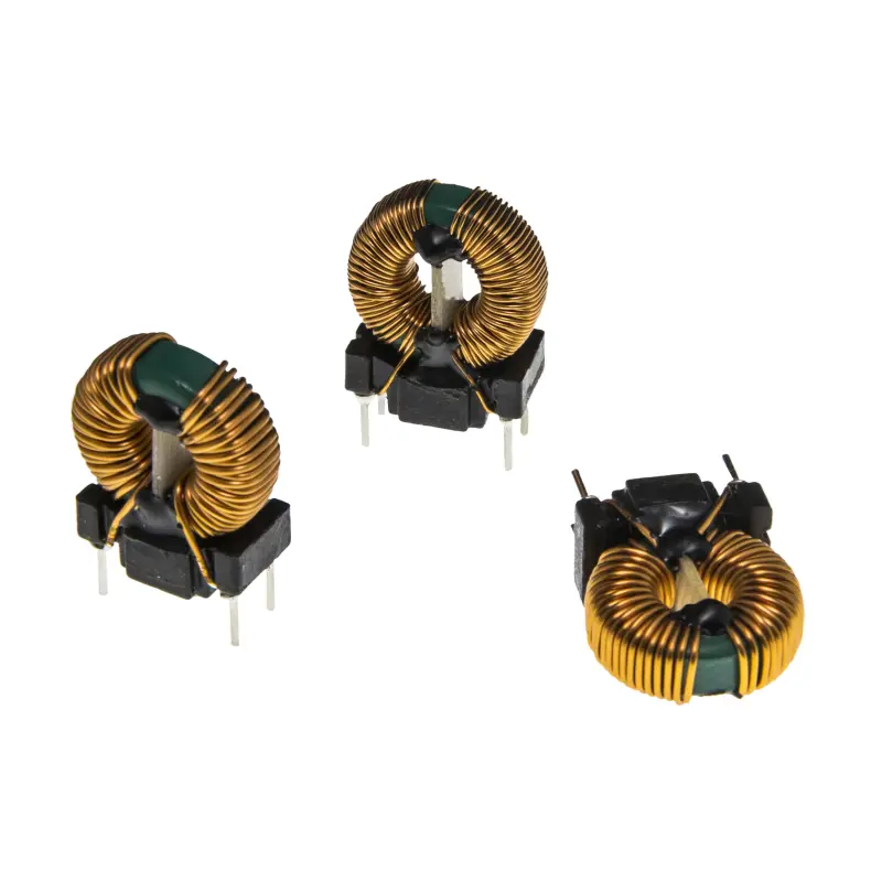
Sendust Toroidal Inductors — the dependable choice for wide-frequency PFC
Sendust offers a gentle DC-bias characteristic and stable high-temperature performance, well suited to TCM schemes whose frequency drops to the 20 kHz range. Inductance and current ratings are customizable.
High-Current Sendust Power Inductors — for 5–10 kW-class front ends
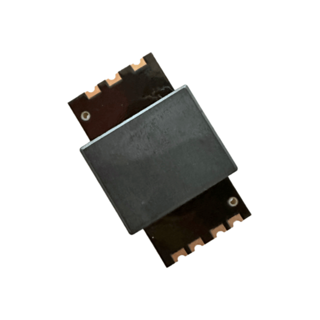
500 µH / 30 A class specifications with high saturation flux density and high Curie temperature, suited to PFC energy-storage inductors in high-power OBC or energy-storage inverters.
Fe-Si Toroidal Inductors — softer bias behavior, better high-temperature endurance
Compared with Sendust, Fe-Si saturates more softly and performs more stably at high temperature, suited to high peak-load-current conditions. Customizable from 10 A to 100 A.
If you take the PC95 route
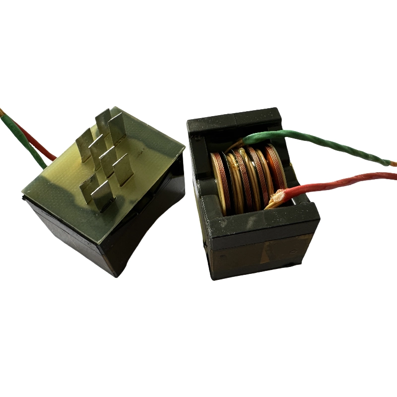
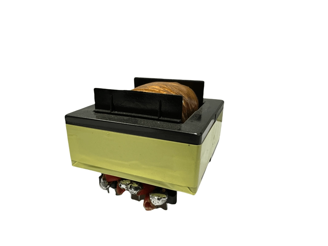
Mn-Zn Ferrite Power Cores — PC95-equivalent material family
PQ / EE / UF power core structures, suitable for gapped PFC inductor designs. Excellent loss performance around 100 kHz, with specifications covering high-power applications.
The final question to settle: is your PFC fixed-frequency CCM, or wide-frequency TCM / CrM? Once you fix the frequency anchor, the choice between these two routes can be made immediately.