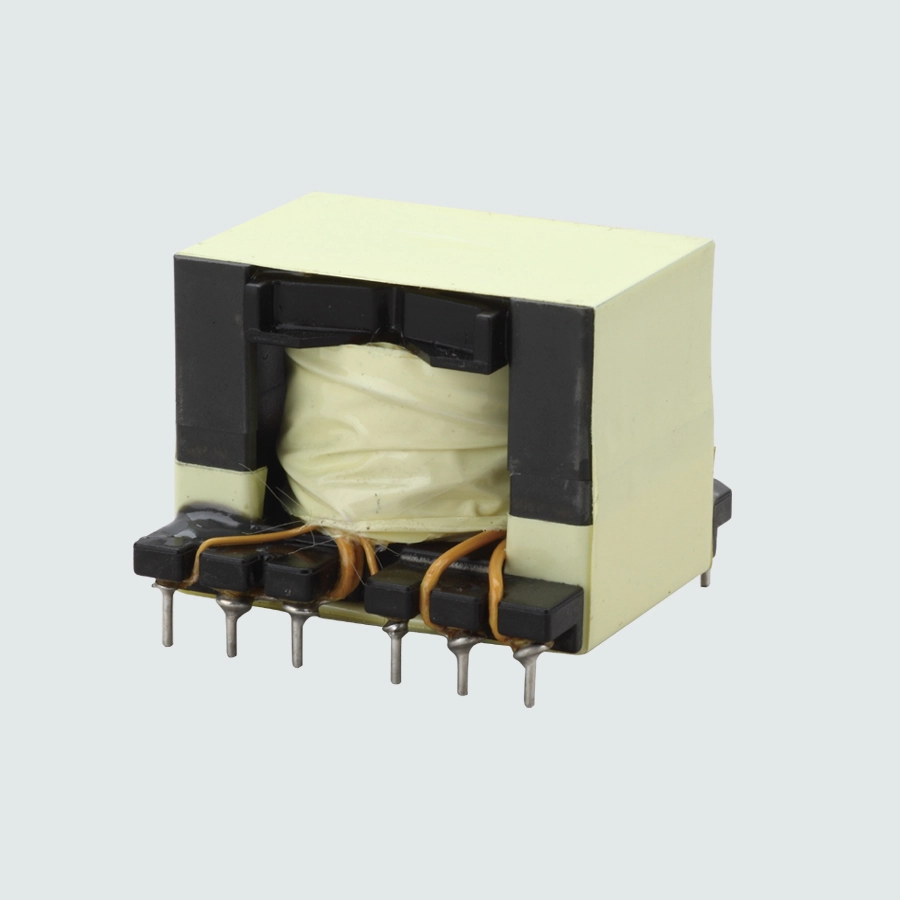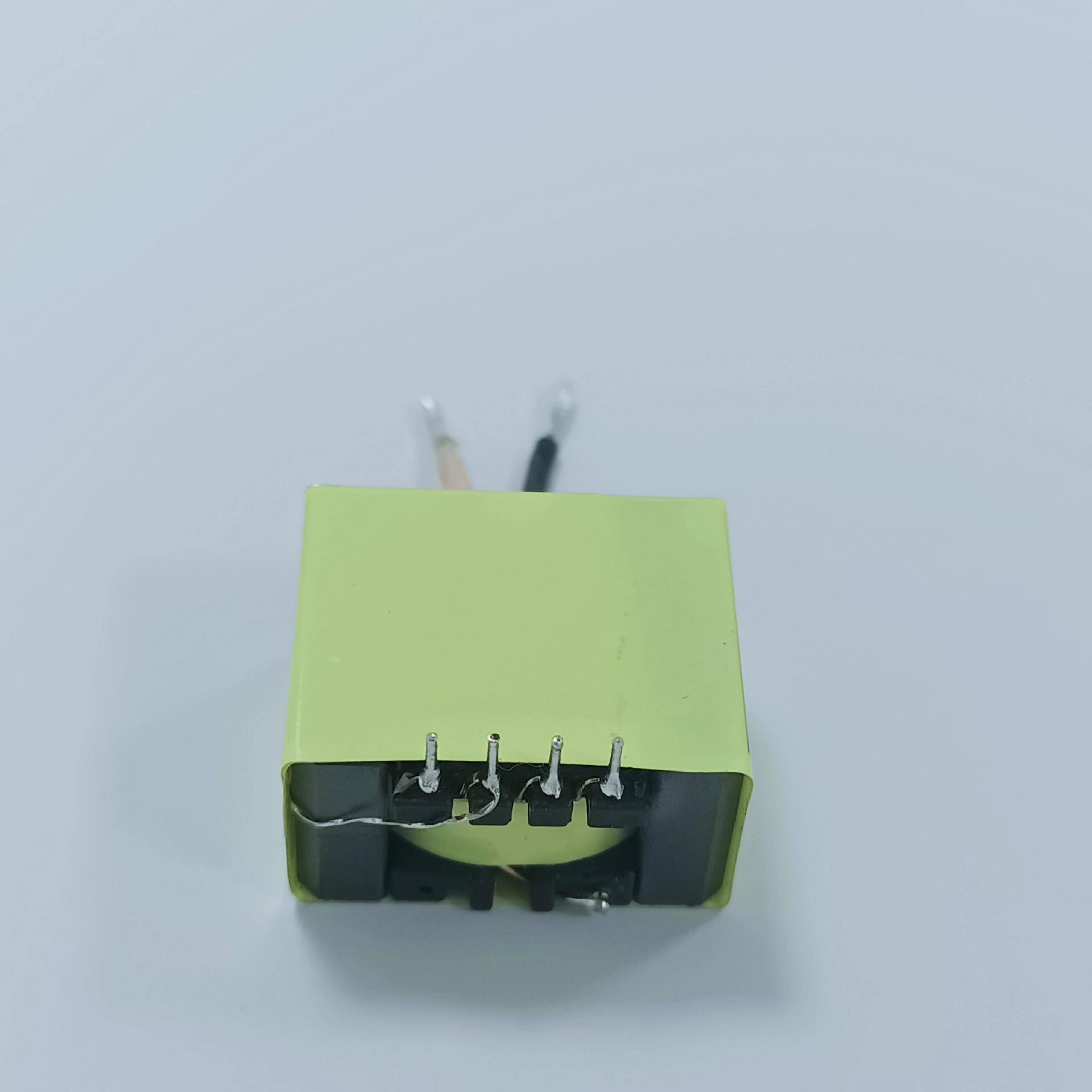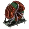
EP7 Auxiliary Gate Drive Transformer
for SiC-MOSFET and IGBT
| Модель: | EP7 SMD |
| Ae (мм2) : | 10 |
| Ref.Power: | 6 W |
Описание товара
The TrafoPSU EP7 series is an auxiliary gate drive transformer for isolated bias supplies in half-bridge and LLC resonant stages. Built on an EP7 ferrite core с split-bobbin — two separate winding chambers — it provides the isolated bias rail that high-side IGBT, SiC MOSFET and GaN gate drivers need, without resorting to a boot-strap or a separate isolated DC-DC brick.
Insulation is achieved by construction rather than by distance alone: the isolated winding uses FIW4 triple-insulated wire, separated from the primary by the bobbin chamber wall and a polyimide barrier film. The result is a reinforced-insulation system verified by a 4.0 kVAC dielectric test at 50 Hz with a 3 mA leakage limit. Three standard builds cover the common 24 V bias rails — 24 V → 20 V / 6 W, 24 V → 12 V / 5 W и 24 V → 48 V / 5 W.
What the specification really buys you is stability at the edges. Every picofarad across the barrier carries displacement current I = CWW × dV/dt, so at a 50 V/ns switching edge a 10 pF barrier injects roughly 0.5 A of common-mode current into the driver on every transition. Holding the barrier to 3.0 pF typical removes about 70 % of it — less driver upset, less radiated EMI, and less shoot-through risk in the half-bridge.
⚡ Основные технические характеристики электрооборудования
|
Параметр |
Технические характеристики |
Примечания / Условия испытаний |
|
Core / construction |
EP7 ferrite, split bobbin |
Two separate winding chambers |
|
Bobbin |
SMD EP7, 8 pins (4+4) |
Lead-free solder termination |
|
Primary inductance |
50 µH min |
10 kHz, 0.1 V |
|
Interwinding capacitance CWW |
3.0 pF typ. |
100 kHz, 10 mV |
|
Turns ratio tolerance |
±2 % |
Across the series |
|
Dielectric withstand |
4.0 kVAC, 3 mA leakage |
50 Hz, core to coil, 2 s |
|
Isolated winding wire |
FIW4 triple-insulated, Ø0.18 – 0.20 mm |
Reinforced-insulation system |
|
Barrier film |
Polyimide, 13 × 14.2 × 0.1 mm |
Between chambers |
|
Bonding / fixing |
Epoxy 808A/B-H, polyester tape 0.025 × 6.5 mm |
RoHS / REACH conformant |
|
Operating temperature Top |
−40 °C to +125 °C |
Компонент |
|
Ambient temperature Ta |
−40 °C to +70 °C |
Application level |
|
Storage temperature Tst |
−40 °C to +85 °C |
Unpacked |
Standard builds
|
Build |
Vin → Vout |
Output power |
Turns ratio N1:N2 |
Leakage inductance (max) |
DCR N1 / N2 (max) |
|
EP7 24 V / 20 V |
24 V → 20 V |
6 W |
1.2 : 1 |
1.95 µH |
85 mΩ / 85 mΩ |
|
EP7 24 V / 12 V |
24 V → 12 V |
5 W |
1 : 0.5 |
1.50 µH |
85 mΩ / 85 mΩ |
|
EP7 24 V / 48 V |
24 V → 48 V |
5 W |
1 : 2 |
3.00 µH |
85 mΩ / 160 mΩ |
Leakage inductance measured at 100 kHz / 0.1 V with the secondary shorted. Primary winding: UEW, 155 °C, Ø0.18 mm × 2P. Other ratios and power levels on request.
Outline
|
Dimension |
Value |
|
Length × width × height |
13.0 ± 0.2 × 14.2 ± 0.2 × 12.0 mm max |
|
Pin pitch |
2.50 ± 0.2 mm |
|
Pin row spacing |
8.69 ± 0.5 mm |
|
Mounting |
8 pins (4+4), SMD |
🛠️ Технические особенности и высочайшее качество изготовления
1. Reinforced insulation built into the winding
FIW4 triple-insulated wire on the isolated winding, the bobbin chamber wall and the polyimide barrier film together form a single insulation system rated to the same protection level as double insulation — recognised as solid insulation under IEC 62368-1 Annex J. No second protective layer elsewhere in the design is required.
2. Barrier capacitance set by geometry, not by luck
Because primary and secondary sit in separate chambers, CWW is defined by the bobbin itself. At 3.0 pF typical it stays there part to part, instead of drifting with winding tension and lay-up — which is what usually happens when the two windings share one bobbin with margin tape between them.
3. ±2 % turns-ratio control
The bias rail follows the turns ratio directly. Holding it to ±2 % keeps the driver supply inside its window across production, without trimming the secondary regulator.
4. Built for the board it goes on
Epoxy-bonded and tape-secured core, polyimide barrier, lead-free terminations and an 8-pin layout with 2.50 mm pitch and 8.69 mm row spacing that follows the standard EP7 gate-drive footprint — so existing EP7-based layouts can generally be re-used. Verified across −40 °C to +125 °C.
🎯 Типичные области применения
- Gate driver bias supplies — isolated bias rails for high-side IGBT, SiC MOSFET and GaN stages
- LLC resonant and half-bridge converters — including open-loop LLC bias designs built around driver ICs such as the TI UCC25800-Q1
- EV charging and traction — on-board chargers, traction inverters and DC-DC converters
- Industrial power — motor drives, UPS, welding inverters, solar inverters and server PSU auxiliary rails