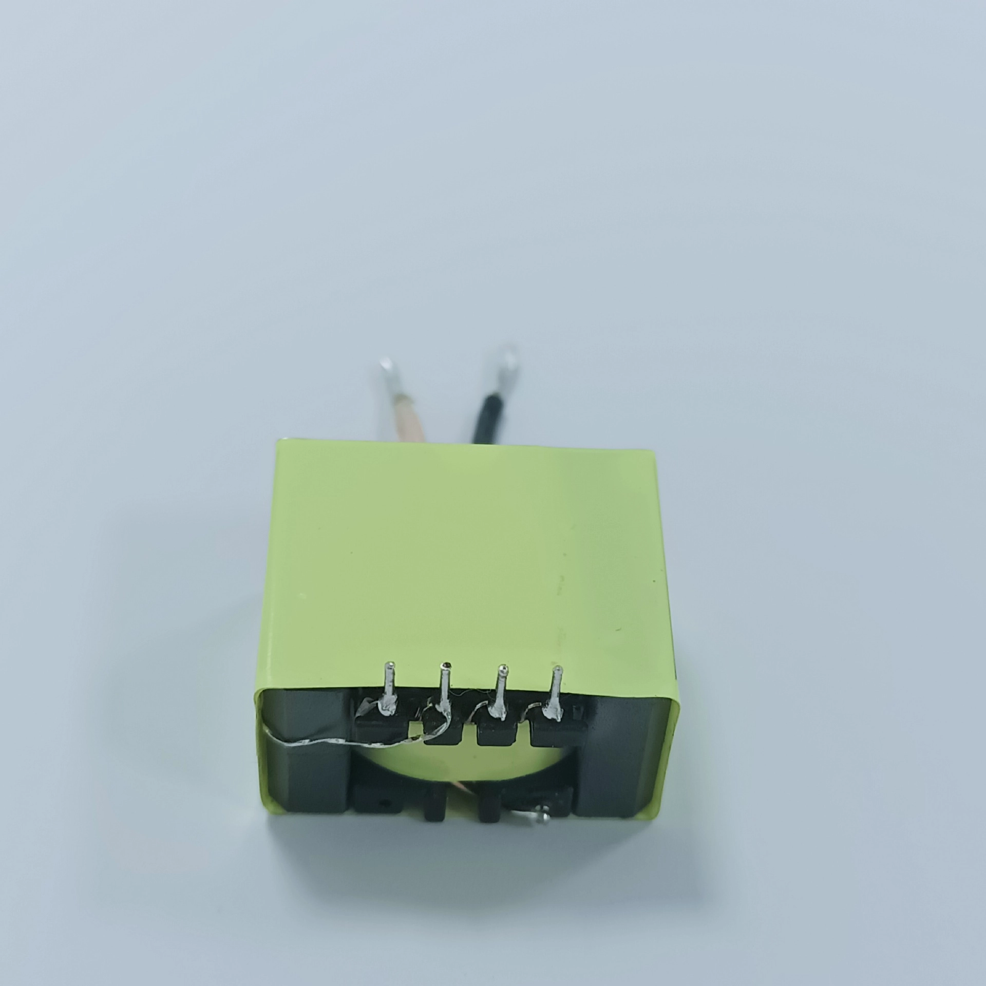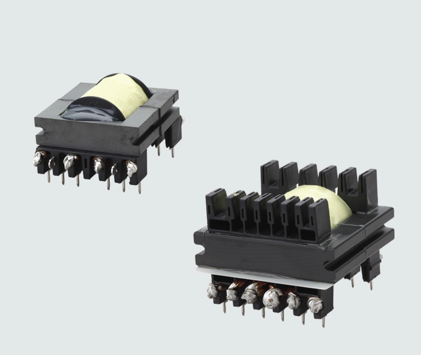
The area product method helps estimate the core size of a high-frequency transformer. Current density determines the copper cross-section needed to carry the winding RMS current. Both decisions must be checked together with insulation space, AC winding loss and temperature rise.
This guide explains the relationship between AP and current density, then follows an illustrative 100 W forward-converter calculation at 150 kHz. The calculations are a starting point for prototype design, not a validated production transformer specification.
What current density controls
Current density J is the winding RMS current divided by the bare copper cross-section. Use the full switching-period RMS current, rather than the average input current or the output DC current, when selecting transformer conductors.
J = Irms / Acu
J is normally expressed in A/mm². Some core charts instead use circular mils per ampere, which is an area-per-current quantity. Convert it explicitly: J ≈ 1973.5 / Dcma. Thus 500 circular mils/A corresponds to about 3.95 A/mm², and 750 corresponds to about 2.63 A/mm².
For one winding of N turns and mean length per turn MLT, the DC resistance and DC copper loss are:
RDc = ρ N MLT / Acu
Pcu,Dc = Irms² RDc = ρ J² N Acu MLT
Use consistent SI units in the resistance calculation: ρ in Ω·m, length in m and copper area in m². With current, turns and MLT fixed, substituting Acu = Irms/J gives Pcu,Dc = ρ N MLT Irms J. Reducing J by half therefore halves DC copper loss in that comparison and doubles the copper area. A square-law comparison applies only when the copper geometry is fixed and current changes.
Current density and window utilization
Ku Aw ≥ Σ(Ni Acu,i)
Ku is the fraction of the selected winding-window area allocated to bare copper. It must allow for enamel, insulation, bobbin geometry, creepage margins, leads and the winding build. Define the window area consistently with the supplier drawing so that bobbin deductions are not counted twice.
Lower J requires larger conductors and more window space. Raising J reduces the required copper area but increases DC copper loss at the same current. It does not increase the window fill. A preliminary Ku of 0.25–0.40 can be useful, but the achievable value depends on the actual construction.
| Cooling condition | Initial J range | Design check |
|---|---|---|
| Natural convection | 2.5–4.0 A/mm² | Check ambient temperature, enclosure and winding hotspot |
| Forced air | 5.0–7.0 A/mm² | Confirm airflow at the transformer and fan-failure conditions |
These ranges are starting assumptions, not allowable current ratings. Insulation thermal class sets a material temperature limit; it does not by itself establish an acceptable operating temperature or service life. At 75 °C ambient, a 130 °C insulation class leaves 55 K to the class limit before additional design margins are applied.
Skin effect and proximity effect
δ = √(ρ / (π f μ₀))
Using copper resistivity 1.72 × 10⁻⁸ Ω·m at approximately 20 °C and μ₀ = 4π × 10⁻⁷ H/m gives the following skin depths.
| 频率 | Copper skin depth |
|---|---|
| 50 kHz | 0.295 mm |
| 100 千赫 | 0.209 mm |
| 150 kHz | 0.170 mm |
| 400 kHz | 0.104 mm |
| 500千赫 | 0.093 mm |
| 1000 kHz | 0.066 mm |
At 150 kHz, δ is approximately 0.170 mm. A wire diameter of about 2δ can be a first screening rule, but it is not a universal limit. Proximity fields, layer count and waveform harmonics can produce significant AC loss even with thin strands.
Litz wire can reduce AC loss when strand diameter, transposition and termination are appropriate. Select strand count from the required copper area and the bundle packing factor. Foil and PCB windings require their own thickness and layer checks. There is no universal frequency at which Litz becomes mandatory or a fixed AC-to-DC resistance multiplier that applies to every winding.
What the area product method estimates
AP = Ae Aw
Ae is the effective magnetic cross-section and Aw is the usable winding window. AP is a geometric product, not a power rating. The conversion is 1 cm⁴ = 10⁴ mm⁴. For example, 91 mm² × 56 mm² = 5096 mm⁴ = 0.5096 cm⁴.
AP sizing combines Faraday’s law, winding RMS current and the window constraint. For a forward transformer, derive the turns from the applied volt-seconds. A gapped-core magnetomotive-force relation is not a general derivation of transformer power capacity.
Np ≥ Vin D / (f ΔB Ae)
Here ΔB is the flux-density change during the on-time, in tesla, and Ae is in m². Do not insert an additional square-wave factor of 4 into this pulse equation. A formula using peak bipolar flux and a waveform factor uses a different convention.
For an ideal CCM forward converter with negligible current ripple, equal J in both main windings and no auxiliary or reset-winding allocation, the load-current estimate gives:
APmin ≈ 2 Pout √D / (f ΔB J Ku)
This expression gives m⁴ when J is in A/m². With J in A/mm², multiply the numerator by 10⁶ to obtain mm⁴. It applies to the stated forward-converter assumptions; flyback energy storage and other topologies require their own treatment. Reserve extra space for reset windings, magnetizing current, insulation and manufacturing tolerances.
As a separate cross-check, Magnetics publishes WaAc = PoDcma/(KtBmaxf), using cm⁴, circular mils/A, gauss and Hz. Its forward-converter Kt is 0.0005 for the stated space factor of 0.4. Keep that convention intact; its Bmax definition and topology assumptions must not be mixed with ΔB in the pulse calculation above.
A 100 W forward converter example
The example assumes a 100 V DC input, 12 V output, 150 kHz switching and CCM operation. It does not assume a 400 V bus. A 1 V effective rectifier drop is used as a simplified estimate. Equal-turn reset is assumed, so the starting duty ceiling is 0.45 to leave reset margin.
| Design assumption | Value |
|---|---|
| Output power and current | 100 W and approximately 8.33 A |
| Initial maximum duty cycle | 0.45 |
| Design flux swing ΔB | 0.15 T |
| Current density J | 4.0 A/mm² |
| Window utilization Ku | 0.40 |
| Illustrative core geometry | Ae = 91 mm² and Aw = 56 mm² |
| Illustrative mean length per turn | 78 mm |
The core dimensions and MLT are illustrative assumptions, not verified data for a specific ETD part. Check the actual core and bobbin drawings before selecting a production component. The 0.15 T flux swing must also be checked against the material loss curves at operating temperature.
APmin ≈ 2 × 100 × √0.45 × 10⁶ / (150000 × 0.15 × 4 × 0.40)
APmin ≈ 3727 mm⁴ = 0.3727 cm⁴
The assumed core has AP = 5096 mm⁴, approximately 1.37 times this preliminary requirement. That is geometric margin, not proof of thermal suitability.
Np ≥ 100 × 0.45 / (150000 × 0.15 × 91 × 10⁻⁶) = 21.98
Choose 22 primary turns. For the forward conversion ratio, the duty cycle is part of the output-voltage equation.
Vout + Vf ≈ D Vin Ns / Np
Ns ≥ 22 × 13 / (100 × 0.45) = 6.36
Choose 7 secondary turns. At 100 V input, the estimated regulated duty is 13 × 22/(100 × 7) = 0.409. The resulting flux swing is approximately 0.136 T. Recheck minimum and maximum input voltage, startup, control limits and reset volt-seconds in the real design.
RMS current wire area and window check
Ignoring magnetizing and reset current and assuming negligible output-inductor ripple, secondary current flows through the transformer during the on-time. The load-related RMS values are:
Is,rms ≈ Iout √D = 8.33 √0.409 ≈ 5.33 A
Ip,rms ≈ (Ns/Np) Iout √D ≈ 1.70 A
| Winding | Turns | RMS current | Bare copper area at J = 4 |
|---|---|---|---|
| Primary | 22 | 1.70 A | 0.425 mm² |
| Secondary | 7 | 5.33 A | 1.33 mm² |
Required copper window ≈ 22 × 0.425 + 7 × 1.33 ≈ 18.7 mm²
Allocated copper window = 56 × 0.40 = 22.4 mm²
The two main windings use about 83% of the allocated copper window, or about 33% of the total assumed window. The remaining allocation must accommodate the reset winding and any other conductors. A drawing-based check of insulation, leads and bundle dimensions is still needed. If these do not fit, increase the window or revise the winding design rather than assuming a higher Ku.
Loss and temperature verification
With the illustrative 78 mm MLT and the selected bare copper areas, the cold DC winding resistances are approximately 0.0695 Ω for the primary and 0.00705 Ω for the secondary. The load-related DC copper loss is approximately 0.20 W in each winding, or 0.40 W total.
This is not the total transformer loss. Add hot-copper resistance, magnetizing and reset-winding loss, AC winding loss, terminations and core loss. Copper resistivity rises with temperature; around 20 °C, its temperature coefficient is approximately 0.0039/K. Core loss must come from the chosen material and excitation conditions, not a generic ferrite power limit.
Measure winding and core temperatures on a prototype at the worst relevant input, load, ambient and cooling conditions. A lumped thermal-resistance estimate can guide the first iteration, but it does not resolve internal hotspots. The example therefore establishes a consistent initial calculation, not a verified efficiency or temperature-rise result.
A practical design sequence
Define input range, topology, reset method, output power and insulation requirements.
Choose a trial flux swing from material loss data and a trial J from the thermal budget.
Estimate AP with a topology-specific expression and consistent units.
Select a core and bobbin, calculate integer turns, then recheck duty cycle and flux.
Calculate full-period RMS currents and check the winding build, including reset and auxiliary windings.
Estimate hot DC and AC winding loss, core loss and parasitics; confirm temperatures on a prototype.
AP narrows the core choices. Current density, conductor geometry, insulation and thermal testing determine whether the resulting transformer is suitable for the application. More turns or finer strands alone do not guarantee lower loss; evaluate the complete winding build.
Custom transformer design support
TrafoPSU designs and manufactures custom transformers and inductors. Explore our SMPS transformers for wound-core power-supply designs, or our 平面变压器 when PCB winding geometry and profile are part of the design requirement.
To review AP sizing, winding construction and thermal constraints for your project, contact our engineering team with the operating conditions and insulation requirements.